Project Requirements
- The device must be constructed of readily available materials that can be purchased from hardware and/or online supply stores. The total cost spent assembling the system cannot exceed $1,000.
- Must be powered using standard batteries are AC 120V 60Hz outlets.
- The total weight of the entire system must not exceed 20 pounds.
- The system must fit within an 18”x13”x10” box (accessory components do not count towards this).
- The component that interfaces with the material being tested, i.e. the probe, should be easily replaceable with an identical part. One such replacement component must also be manufactured. The cost of the component cannot exceed $150.
- The device must be able to measure the thermal conductivity and bulk liquids and solids within 5% of reference values.
- The device must measure the thermal conductivity within 15 minutes of initiating the measurement.
- Measurement preparation time should not exceed 45 minutes.
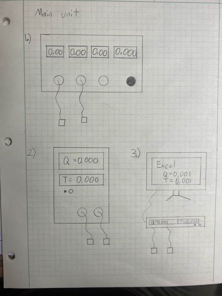
- The device must retain measurement data or plot data to a .xslx file. Key data points to retain are the initial and final material temperature, and heat flow. Other pertinent data, i.e. material surface area, can be manually inserted by the user.
- The device must have a live display showing measurement progress in real time. The displays must have a refresh rate greater than 60 Hz. At least two displays are necessary which show change in temperature and heat flow respectively. Furthermore, an indicator light must be present to show when a measurement is in progress or complete
The final Thermal Conductivity Meter product will be an electrical assembly united by structural members which conducts heat transfer analysis.
Electrical
The TCM will have several electrical systems synthesized together. The microcontroller will require programming and power analysis. A Wheatstone bridge and several Ohm’s law calculations will be needed to extract heat energy transfer and temperature measurements from the probes. Power transformation calculations will be necessary to direct safe amounts of power towards the probes and components.
Structural
The TCM needs a housing and two different mounts for the probes. The housing will not bear much load but Mechanics of Materials principles can be applied to create the best balance between lightweight and strength. Each probe will need to be adapted for its respective material type; solids and liquids. The liquid probe structure can be united with a standard container’s lid to help create an optimal closed environment. Since it will have an elongated shape, shear, deflection, and torsion calculations can be done to ensure a sound design. The solid probe will take measurements from a much more “open” environment than the liquid probe. It will be smaller and may not require as many Mechanics analyses, but will certainly need more heat transfer calculations.
Heat Transfer
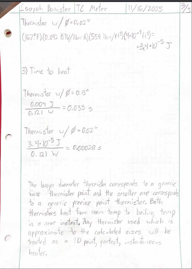
Accurate conductive heat analysis form the backbone of this project’s success criteria. The thermistors used in each probe will need analysis based on the heat transfer of their material and cross section. Each factor in the thermal conductivity equation shown on the home page will need to be precisely controlled in the measurement and construction of the TCM.
Analysis 1 – Controlling Factors to Match Fourier’s Heat Conduction
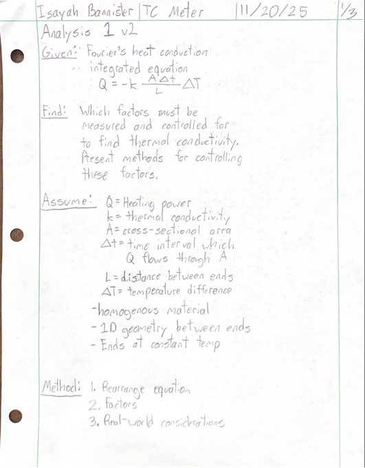

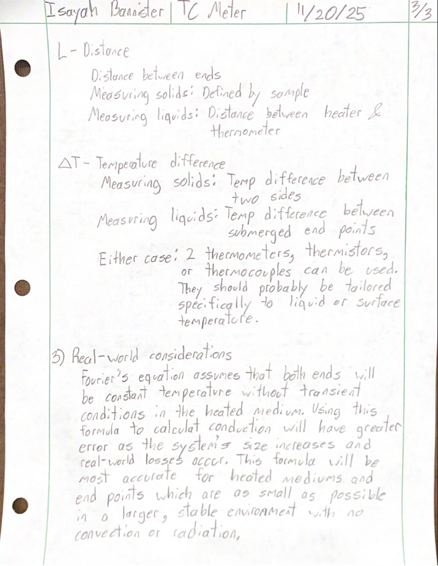
The integrated form of Fourier’s Law which assumes 1-dimensional heat conduction through a homogeneous medium and two end points at a constant temperature is the simplest formula which can be used to find the thermal conductivity of a material. This analysis found all factors which the TCM should control for in its measurement. These are all feasible, but must also factor in real world complications which are not included in Fourier’s equation. This includes losses through convection and conduction, transient conditions, and differences between a “lumped” and “non-lumped” system. The sizes of the conduction medium, the end points, and the measuring environment should be engineered into a system most conducive to assuming 1-dimensional, lossless, lumped conduction.
Analysis 2 – Sufficiency of Arduino Uno Rev3 Supplied Power

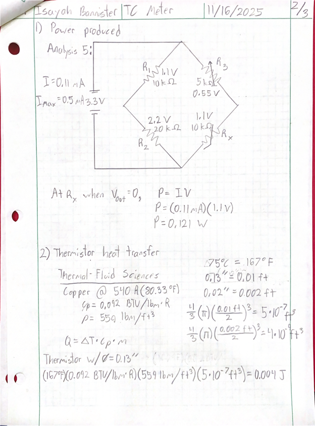
The Arduino Uno R3, which is the proposed system controller, has two power ports. The port which operates the least of the board’s functions and has the highest resolution is the 3.3V port. Since this port will be used to power several heating and measuring components, analysis was necessary to ascertain if the supplied power would be sufficient. Given the Wheatstone bridge proposed in Analysis 2.g.5, it was found that the bridge drew 0.121 W of power. This is within the 0.165 W maximum of the port, concluding that 3.3V is sufficient.
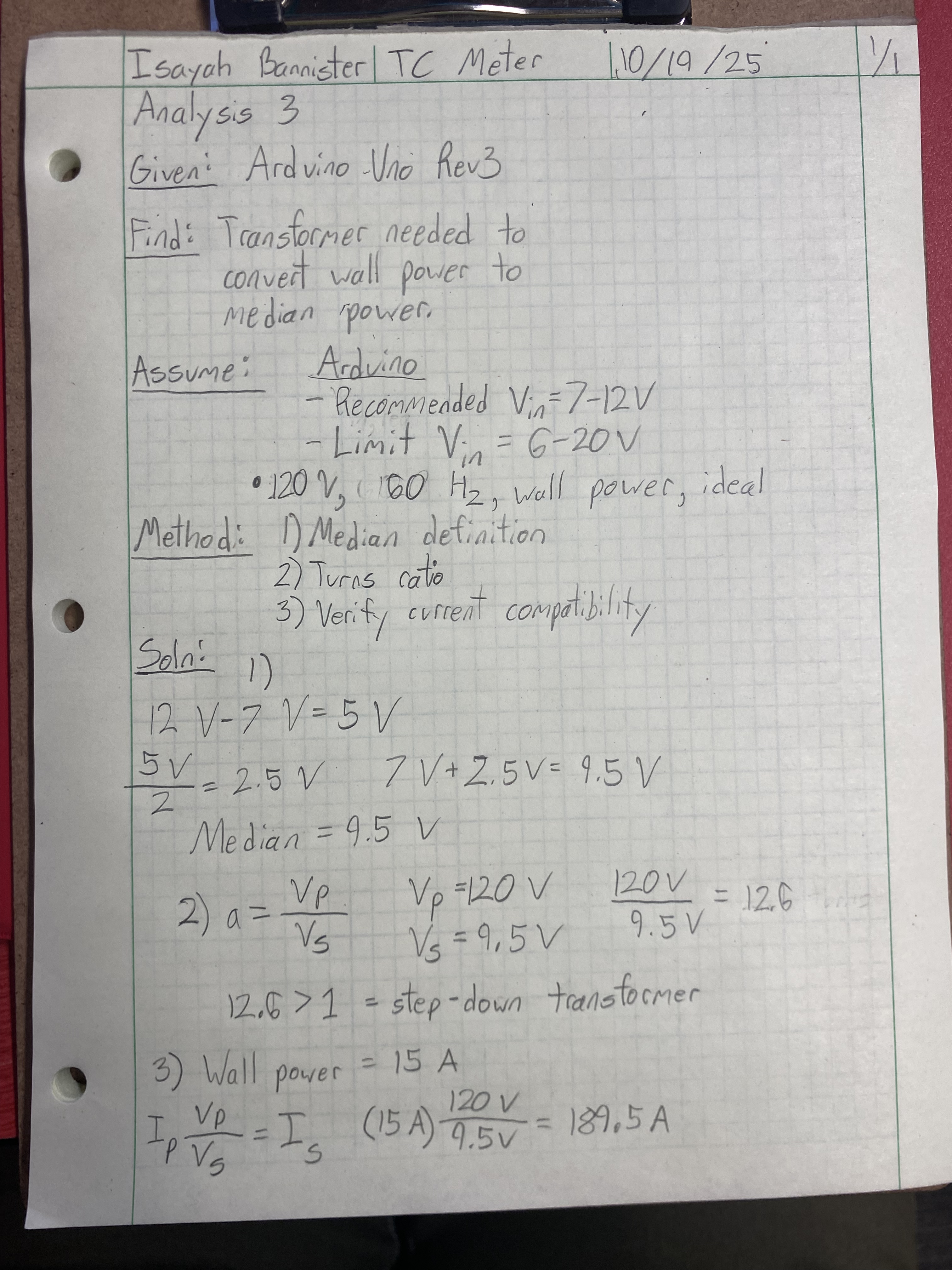
Analysis 3 – Wall-Arduino Power Transformer
According to Requirement 2, the TCM must be capable of utilizing either standard batteries or 120V 60Hz outlet power. Outlet power was chosen as the source of choice to remove any concerns about battery lifespan. The Arduino Uno Rev3 is only recommended to receive 7-12 volts to its power port. The median recommended power value is 9.5 volts, which requires the wall power to go through a step-down transformer. The transformer was calculated as needing 12.6 turns in an ideal setting in order to convert 12V to 9.5V. Since the wall uses AC, the stepped-down current was calculated to be 189.5 amps ideally.
Analysis 4 – Liquid Probe Thermistor Standoff Deflection
The TCM must produce measurements to within 5% accuracy of reference sources. To meet this (Requirement 6), all factors in the thermal conductivity equation, which can be seen on the home page, will need to be tightly controlled. This analysis concerns controlling the distance over which heat transfer occurs, which means controlling the distance between the probe’s two thermistors. The thermistors will be on the end of extended rods. These rods are meant to mantain a constant distance between the two, but cannot do so if they deflect or are broken. Using material properties (Appendix 9 of Mott et. al.’s Machine Elements in Mechanical Design, 6th Edition), section properties, and cantilever deflection formulas, the force needed to deflect the rods were found. To deflect the rod by 1/16 inch, 426.1 pounds of force are necessary. This is a large amount of force to cause a small amount of deflection, meaning that there should be little concern over the distance being changed as a result of deflection.

Analysis 5 – Wheatstone Bridge Balance
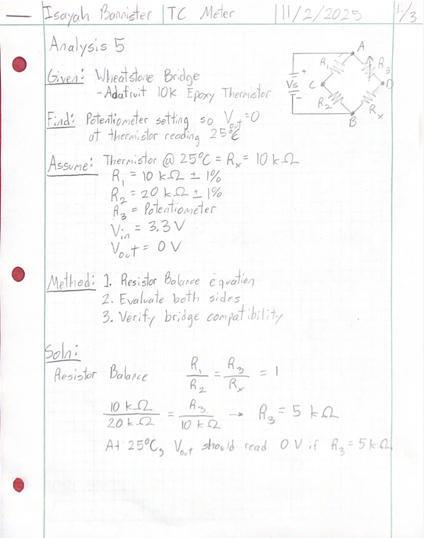
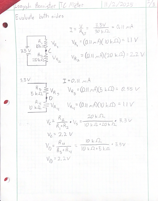

Both probes will have two thermistors. One thermistor will act strictly as a thermometer and be wired on its own circuit. The other thermistor will act as a heat source and will be wired in a Wheatstone bridge, which will allow accurate power delivery to the thermistor. Aside from the thermistor, the bridge will consist of two resistors and a potentiometer. The resistors chosen will be rated for 10 kΩ and 20 kΩ. The analysis found that at room temperature, the bridge will be balanced with no voltage output when the potentiometer is set to 5 kΩ. The analysis also concluded that the current through the bridge would be 0.11 mA, which is within max 50 mA rating for the Arduino’s 3.3V power port. These results verified that the chosen resistors would work and that the Arduino will be able to operate the bridge.
Analysis 6 – Liquid Container Lid Clamping Force
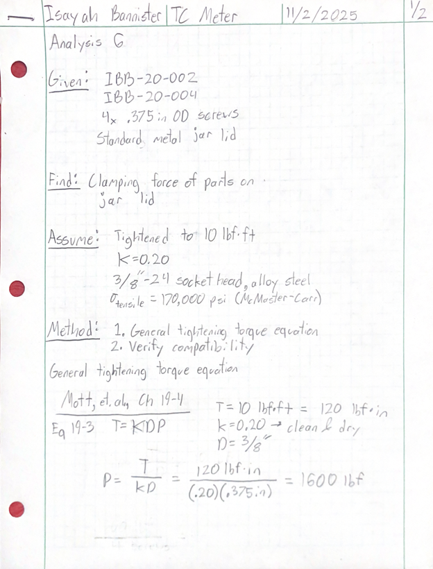
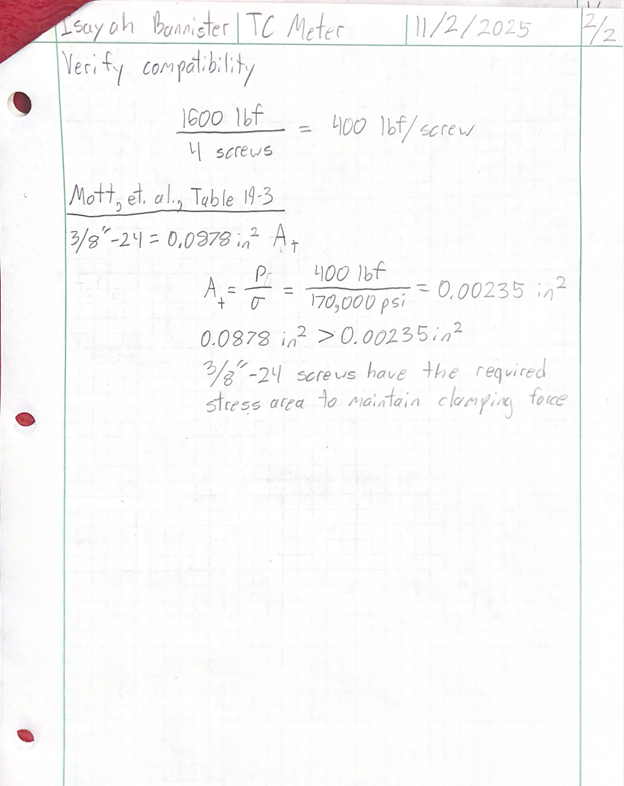
To measure liquids, the probe must be submerged. Using a sealable container as the measuring environment offers the advantage of diminishing radiation and convection heat transfer. The container chosen was a jar, since they come with standard lids which can be cheaply replaced. To attach the probe to the jar lid, a 4-screw clamp will be used. The analysis concerned whether 3/8” screws would be able to withstand each being torqued to 10 lb-ft. It was found that the screws had sufficient stress area to maintain the clamping force.
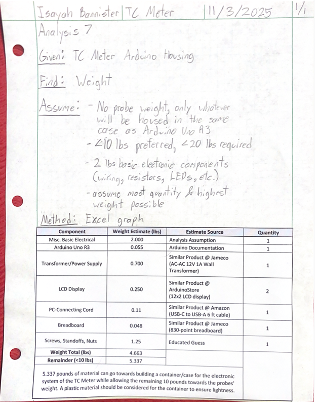
Analysis 7 – Electrical Computing System Weight
According to Requirement 2, the TCM must be capable of utilizing either standard batteries or 120V 60Hz outlet power. Outlet power was chosen as the source of choice to remove any concerns about battery lifespan. The Arduino Uno Rev3 is only recommended to receive 7-12 volts to its power port. The median recommended power value is 9.5 volts, which requires the wall power to go through a step-down transformer. The transformer was calculated as needing 12.6 turns in an ideal setting in order to convert 12V to 9.5V. Since the wall uses AC, the stepped-down current was calculated to be 189.5 amps ideally.
Analysis 8 – Characteristic Length of Solid Sample
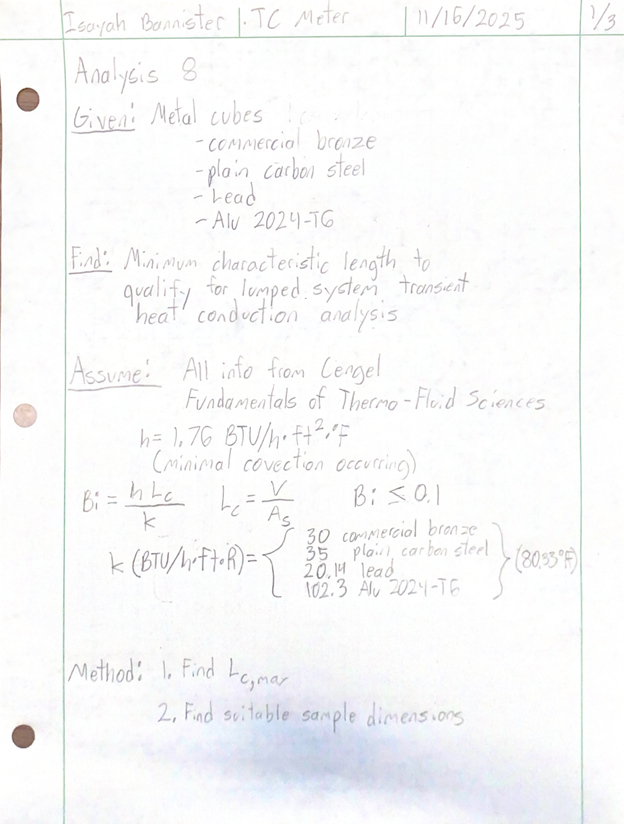
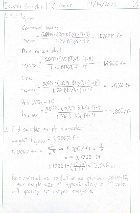

TCM will have a probe meant for measuring solid materials. Requirement 1.d.7 states that a “bulk” sample of characteristic length greater than 1 cm must be used. The analysis sought to find what the maximum characteristic length for the sample could be for it to still be considered part of a “lumped” system. Characteristic length is a factor in calculating the Biot number for the sample, with a Biot number <0.1 indicating lumped analysis is possible. In a lumped system, the sample can be considered to heat uniformly throughout without any discrepancies. A lumped system is advantageous for TCM since it simplifies the equations needed to find thermal conductivity. It was found that for a material as conductive as aluminum, a cube as large as 2 inches would qualify for lumped analysis.
Analysis 9 – Thin-Film Thermistor Bending
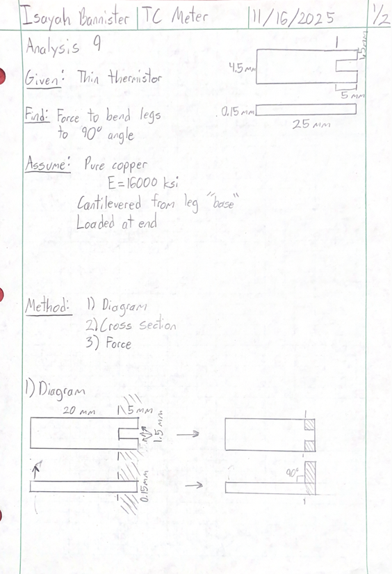
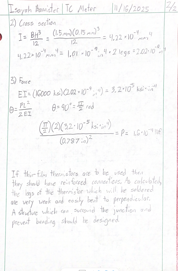
Analysis 2.g.8 concluded that a 2-inch cube fulfilled requirement 1.d.7 for material size. The thermistors which will be used to measure material that small are generally flimsy and easily deformed. Bending analysis based on the dimensions of a commercially available thin-film thermistor found that only 0.00016 lbf is needed to bend it to a 90° angle. This bending occurs at the soldering junctions of the thermistor. The proposed solution to this are components IBB-20-007 and IBB-20-008. These components will be glued around the junctions of the thermistor and help to prevent bending.
Analysis 10 – Total Power Drawn
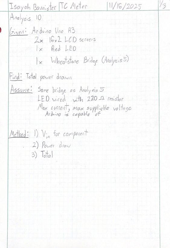
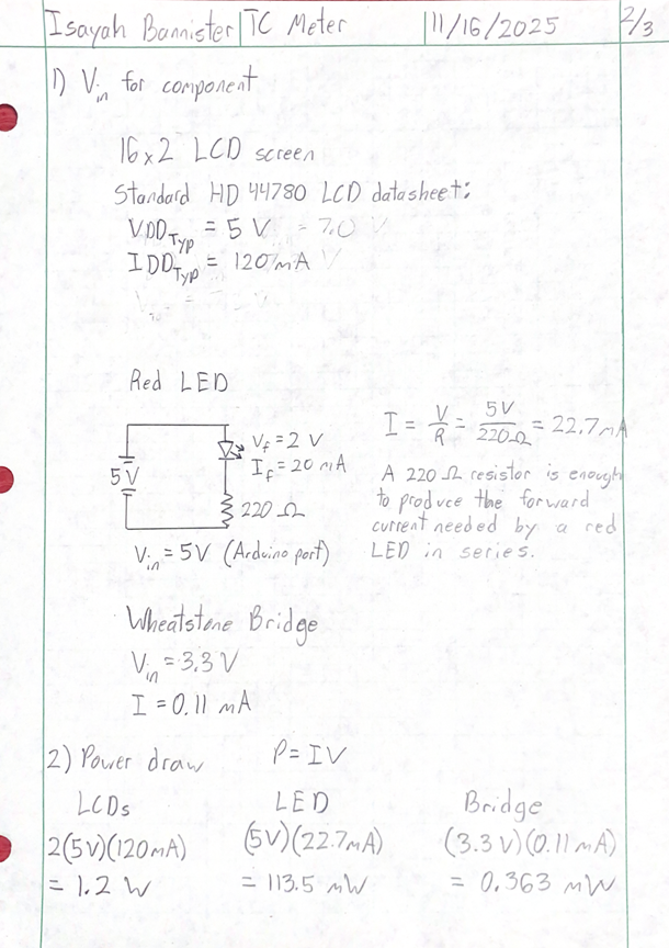
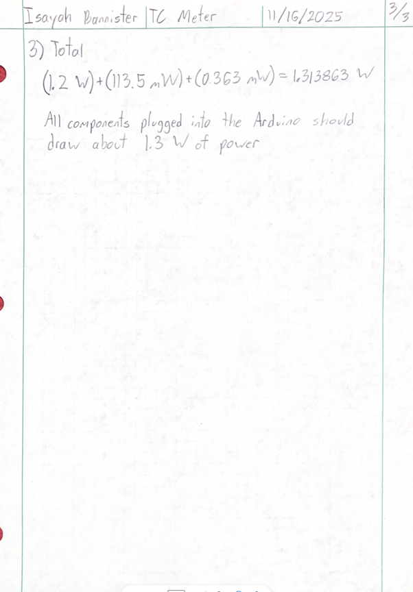
The TCM uses a standard wall outlet for power. Analysis using Ohm’s law estimated that the total power draw of every component attached to the Arduino Uno R3 was 1.3 W. The power supply used is rated to send 12 W max power to the Arduino, meaning that the power used is roughly a tenth of the maximum power supplied.
Electrical System Analysis